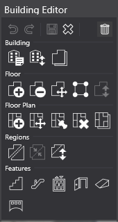
Building Editor
The building editor in NEON Command allows users to create and edit buildings which are an essential part of almost all NEON functionality. This editor has a wide range of tools to help users model their buildings as accurately as possible. Even complex buildings such as convention centers, transit hubs, and theaters can be modeled with the available tools.
A building in NEON consists of multiple distinct parts. Creation of a building begins with an outline of the building and information about the number of floors. The outline of each floor can then be edited separately as needed. Users can add a floor plan to each floor. Structural features such as stairs and elevators can be placed inside the building to improve tracking accuracy.
This article will explain how to use each of the tools in the building editor and how they can affect performance. Each row in the building editor toolbox is addressed in its own section.
NOTE: For help creating more complicated buildings, please see the Complex Building Tutorial.
Outline Creation
TIP: Building Data can be imported from Open Street Maps (OSM) instead of manually created. See OSM Import.
Buildings are created by tracing the outline of a building from a top-down view. Each corner of the building becomes a vertex in the outline. Once the building is fully traced, the user will be left with a polygon that resembles the building, and this shape will be used as the first/ground floor. As additional floors are added, they will use this outline. Each floor’s outline can be edited individually if needed.
To create a new building, select “Tools > Create Building” or right click on the base map in the visualizer and select “Create Building”. This will launch the building editor, which is noted by the toolbox and the orange banner across the top of the window. Moving the cursor over the visualizer shows a blue dot under the cursor and a pair of coordinates to the right of it.
To begin, left click to place the first vertex of the building. Next, click on each successive corner of the building. It is important not to skip corners while making this outline. Once three vertices have been placed, the interior will become semi-opaque to represent the building. If two walls of the building intersect, the interior will become transparent to represent that the building is invalid and cannot be saved.
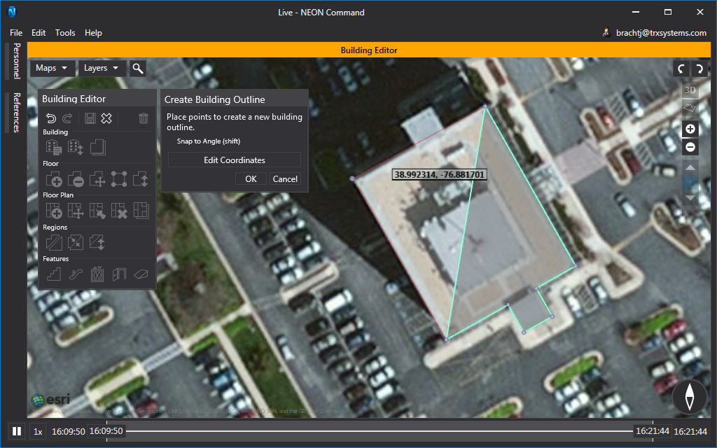
TIP: After placing at least two vertices, hold “Shift” to help create 90° corners. Holding “Shift” while placing a vertex will snap it to a line that is a multiple of 15° from the previous line.
Click the “Edit Coordinates” button to bring up a list with the coordinates of each vertex. These can be edited as needed. This tool is particularly useful when creating a new building that does not appear in any of the base maps.
Once a building outline is valid and complete, press “Enter” or click “OK” to confirm it. This will open the “Edit Building Details” box.
OSM Import
This tool allows users to scan an area for buildings available in a public data set. The data set is maintained by OSM and supports 2D and 3D building models around the world. The availability of buildings, 3D data, and additional building information is determined by OSM.
To import a building from OSM, right-click the visualizer while viewing in 2D and click the “Scan OSM Buildings” option. After scanning for a few seconds, this will display the available OSM buildings in the area. OSM buildings have a black and yellow outline with a gray fill. Left-click on a building to download the available data and launch the building editor.
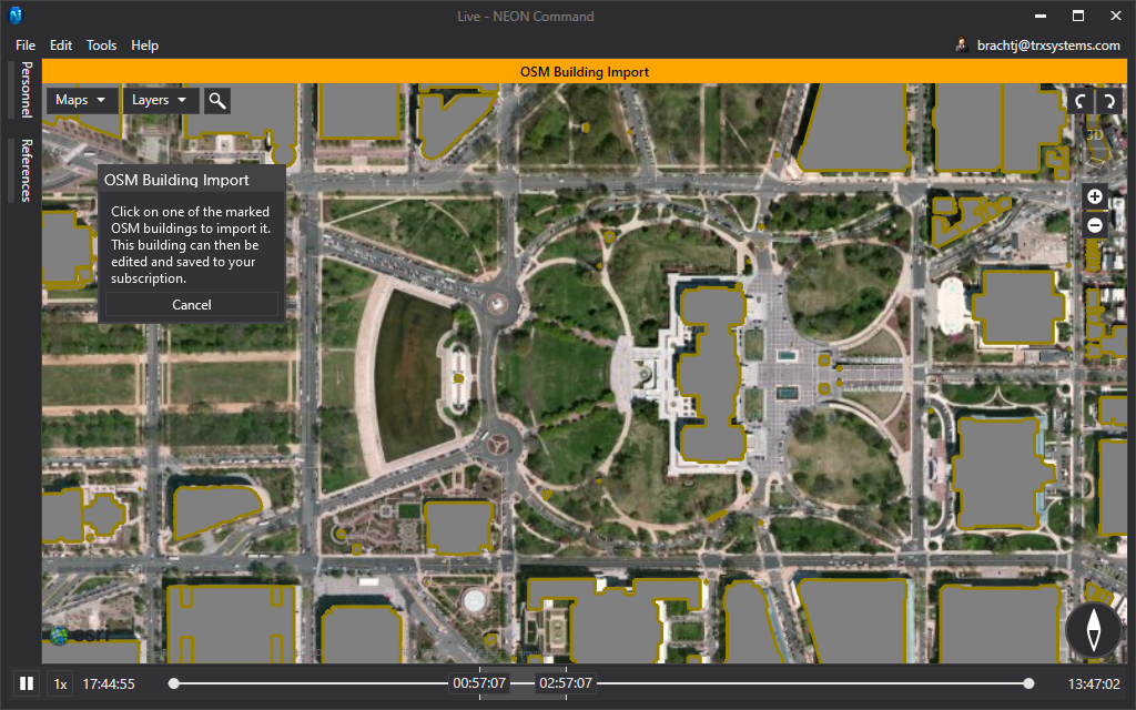
NOTE: Only import buildings that will be actively tracked in. Excessive building models may decrease performance.
Building
This section pertains to the tools listed in the Building row of the building editor toolbox. These tools affect the building as a whole.
Edit Building Details
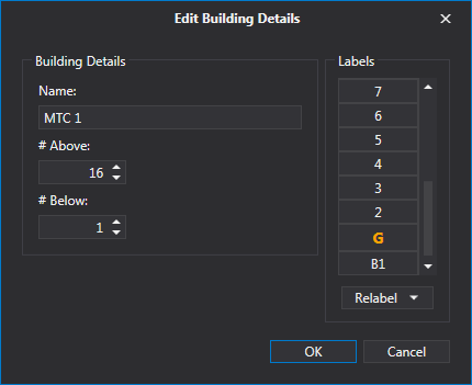
This feature allows users to set the name of their buildings and add floors. All buildings must have a name to be saved. By default, buildings have 1 Above floor and additional floors can be added above (max 200) or below (max 20). The original floor is considered the primary floor, is colored orange, and will be used as the building outline when the building is not selected. Floors can be relabeled to fit either North American or European standards by selecting either from the “Relabel” drop down. A floor can be given a custom label of up to three characters by selecting it in the list of floors.
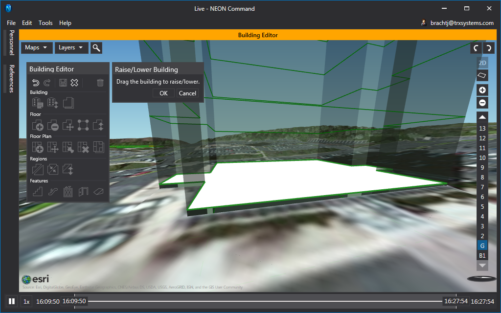
Raise/Lower Building
This feature allows users to raise or lower a building to match entrances to terrain better. It can also be used to lower a building below the surface for underground buildings. Effects from this tool will be purely visual and are not necessary to improve tracking accuracy. To use it, simply click and drag the building up and down while viewing it in 3D.
Copy Floor Layout to Other Floors
With this feature, users can copy the outline and regions of the selected floor to any other floor in the building. Floors that already have the same layout as the selected floor will be grayed out. This can be particularly useful in situations where the first floor is different from most of the other floors. Users could change the layout of the second floor and then copy it to all of the floors above it, which would leave the first floor unchanged.
Floor
This section pertains to the tools listed in the “Floor” row of the building editor toolbox. These tools affect only the selected floor.
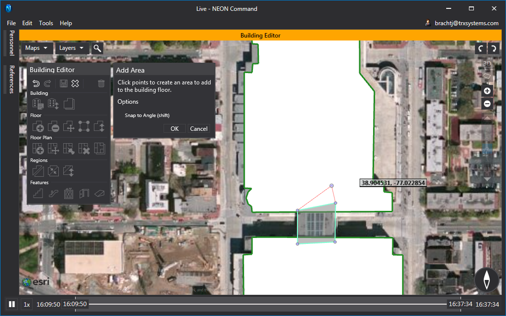
Add Area
This tool can create and add an area to the selected floor. This new area can be either connected or disconnected from the existing area. This tool is useful to add overhangs or for buildings with multiple towers. The tool works much like creating an outline. The user must add at least three vertices and have a valid polygon.
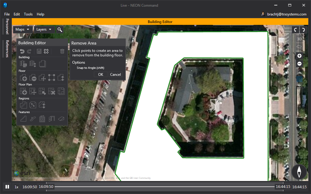
Remove Area
This tool removes an area from the selected floor. This tool is particularly useful to trim the outline of a building or for buildings with courtyards. The tool works much like creating an outline. The user must add at least three vertices and have a valid polygon.
Edit Layout
Users can use this tool to translate, scale, stretch, and rotate the outline of a floor. Click and drag inside the outline to translate. Click and drag the control handles around the outline to scale and rotate, or hold “Shift” while doing this to stretch it.
NOTE: Use this to align the outlines with the base of the building. Because satellite images are taken at an angle, the roof of a building and its base are not lined up. This causes an issue when tracing the roof of a building because it is being traced in the wrong location. For best results, first trace the roof of the building and add all of the floors, then move the first floor to match the base, and then copy this outline to all other floors. If this is done before editing other floors, it will be very helpful in keeping each floor aligned.
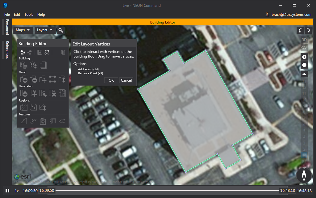
Edit Layout Vertices
The “Edit Layout Vertices” tool can be used to reposition vertices as well as add and delete them. Click and drag vertices to move them. Hold “Ctrl” and click on the outline to add a vertex. Hold “Alt” and click on an existing vertex to remove it.
Raise/Lower Floor
With the “Raise/Lower Floor” tool, users can raise or lower a floor to represent a height that is different than normal. Changes in floor height are purely visual and will not affect tracking accuracy. This can also be useful if a building has entrances on multiple floors. It will allow users to align multiple floors with the terrain at each entrance. This tool will not be available while selected to the 1st floor.
Floor Plan
This section pertains to the tools listed in the “Floor Plan” row of the building editor toolbox. Floor plans do not directly contribute to a user’s location accuracy. However, they are an important reference in many other aspects of the system. They have a very large indirect effect on accuracy. It is highly recommended to use accurate and properly scaled floor plans.
Add Floor Plan
Use this tool to add a floor plan to the selected floor. The floor plan can be either a .jpg, .jpeg, .png, .bmp, or .gif file. When a floor plan is added, it will be oriented north-up by default.
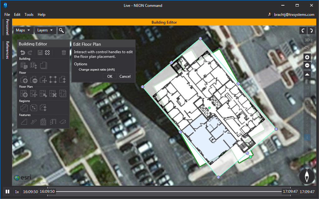
Edit Floor Plan
Users can use this tool to translate, scale, stretch, and rotate the floor plan. Click and drag inside the outline to translate. Click and drag the control handles around the floor plan to scale and rotate, or hold “Shift” while doing this to stretch it.
NOTE Right click to set “Origin”. This sets a new point in the floor plan that can be the center of scaling, stretching, and rotating.
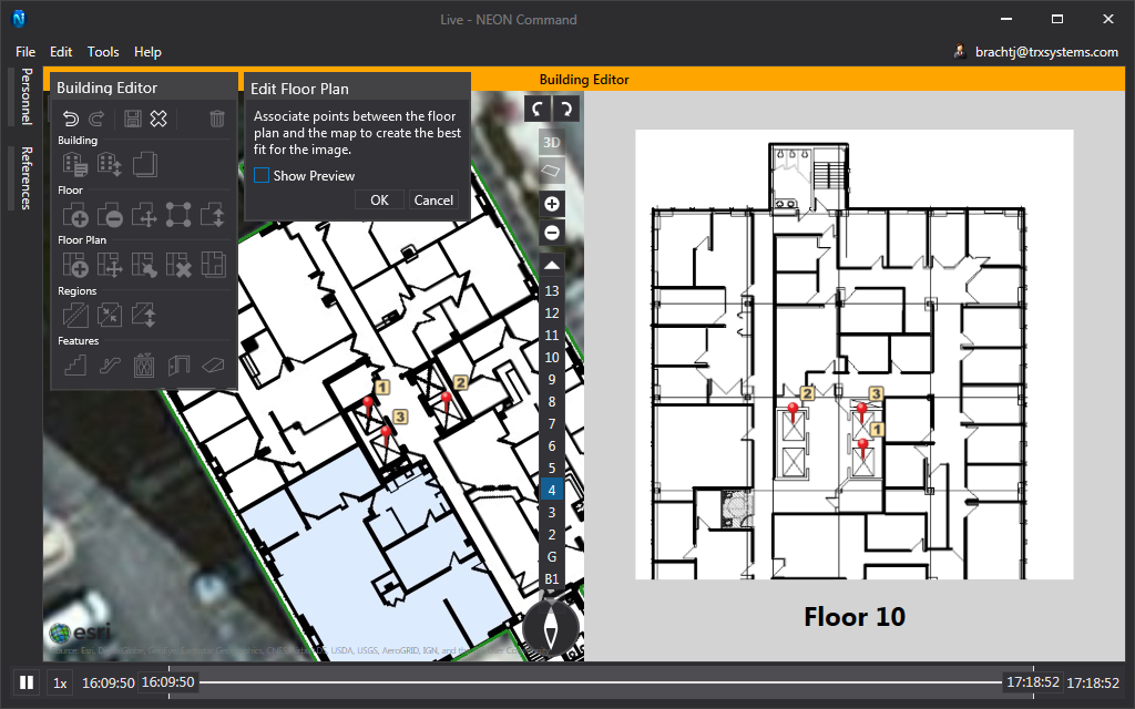
Edit Floor Plan with Control Points
Often, publicly-available floor plans are not to scale and do not necessarily line up well with a building outline. Control points allow the user to set known locations of the floor plan. Setting multiple control points will stretch and scale the floor plan to fit these points as best as possible. This can be useful for things such as aligning stairwells and elevators on multiple floors.
Selecting this tool will split the screen into two parts. On the left will be the worldview and, on the right, will be the floor plan view with the selected floor. To orient the floor plan, set control pairs by clicking a known location in the worldview or floor plan and then clicking the corresponding point on the other view. Users can click the “Show Preview” check box in the toolbox to overlay an image of the selected floor’s floor plan. After creating a few control points, the floor plan should line up relatively well. Correspond the selected floor plan to other floor plans, by choosing a different floor in the floor selector in the worldview. No more than five control pairs can be created.
Delete Floor Plan
This button will remove the floor plan from the selected floor.
Copy Floor Plan to Other Floors
Often, tall office buildings or apartment buildings will have a similar floor plan on multiple floors. This tool allows users to copy an already placed floor plan to any other floor. The floor plan will be copied with the same orientation which means that stairwells and elevators will be perfectly aligned across these floors.
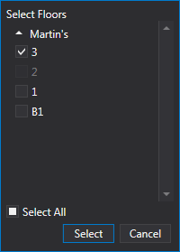
To use this tool, select the floor with the floor plan to copy, then select this tool. In the floor selector that opens, select each floor to get a copy of the floor plan and click “Select”.
Regions
This section pertains to the tools listed in the Regions row of the building editor toolbox.
Regions allow users to create areas on a floor that are separate from the rest of the floor. These regions can be raised and lowered as needed, and features such as stairs and ramps can be placed to connect regions. Regions are particularly useful for things such as split levels, stages, and some staircase landings.
TIP: Create a region for a staircase landing if there are three or more sets of stairs connected to it. While this design is uncommon, this idea is useful for creating stair shapes that are not supported by NEON.
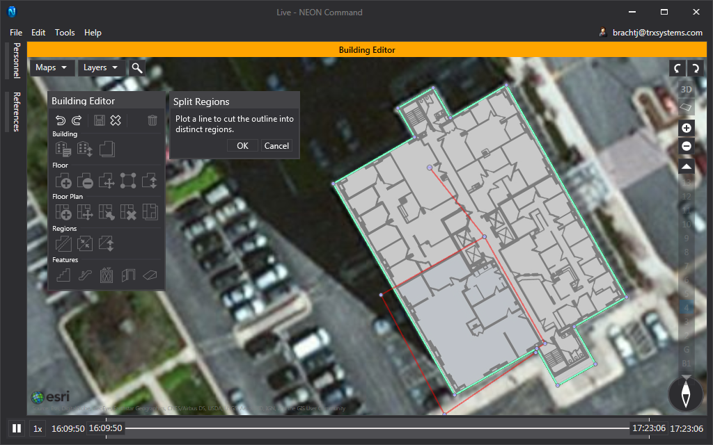
Split Regions
Use this tool to create new regions. After selecting the tool, a vertex will appear below the cursor. Click to place the vertex in the desired location. Continue placing vertices to create lines that cross across existing outlines and regions. Any complete polygons that are created by intersecting lines will become regions after clicking “OK”. Line segments that terminate at another line will be discarded.
Merge Regions
This tool allows users to create a single region by merging multiple adjoining regions. Only regions that are next to each other can be merged.
When using this tool, click inside a region to select it and it will turn blue. Click in it again to deselect it. Once the appropriate regions have been selected, click “Merge” to complete.
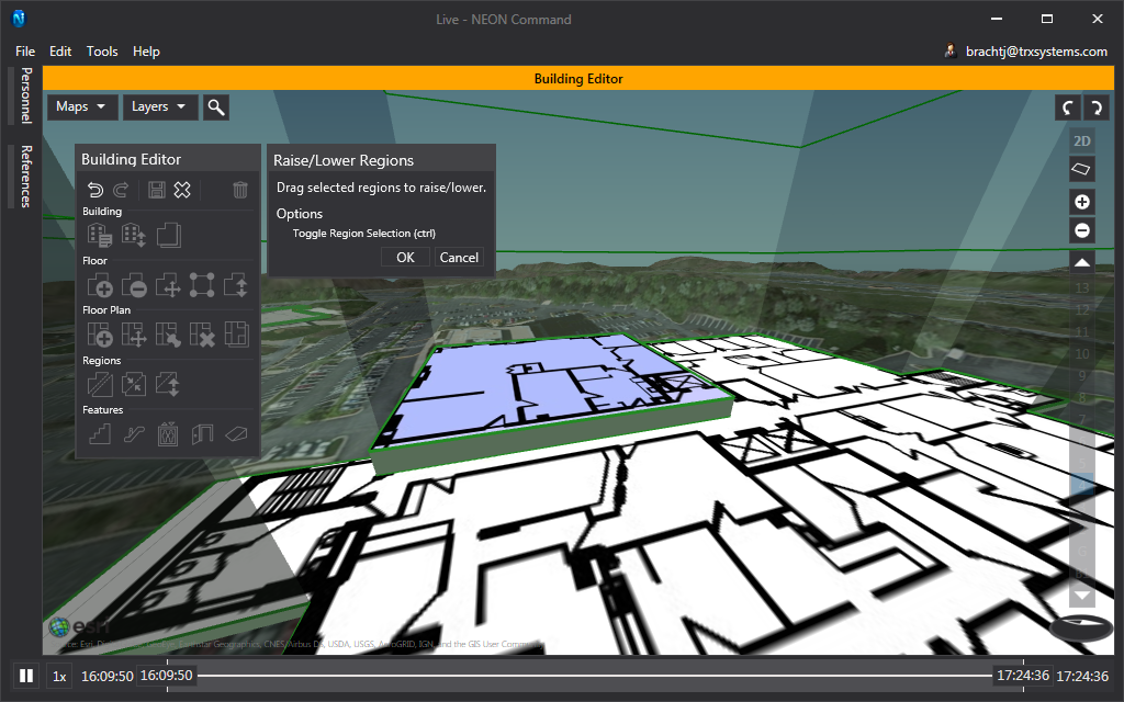
Raise/Lower Regions
Users can use this to raise or lower a region to represent a height that is different than normal. Changes in height are purely visual and will not affect tracking accuracy.
To use this, select the tool, then click on the region to elevate. With the region selected, click inside the region and drag it up and down. Hold “Ctrl” to select multiple regions at once. This is recommended if two regions are known to be the same height.
Features
This section pertains to the tools listed in the Features row of the building editor toolbox.
In NEON, Features are used to represent structural features such as stairs and elevators. Features can be detected as a user walks in them and they are used to constrain the user’s location. These feature constraints are very important to keeping users’ locations accurate as they spend time in a building.
When features are placed in NEON Command, they will be gray to indicate that they are unmapped. Using the Mapper app, users can walk through these features to merge in additional data about them. After this, features will be considered mapped and will turn green. To edit a feature once it has been placed, right-click on it and select the feature edit option.
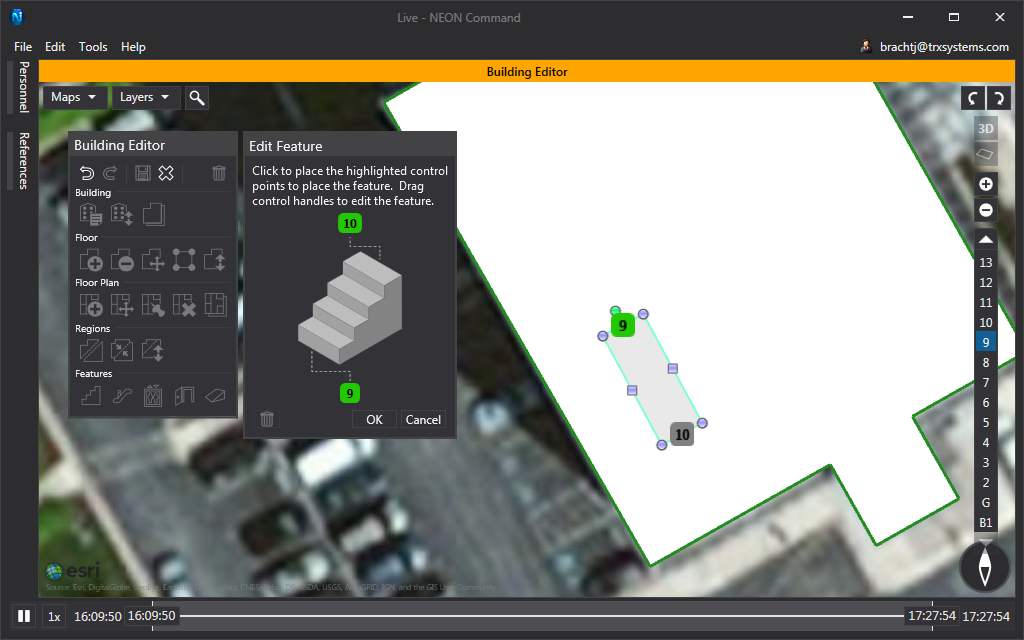
Stairs
Clicking on the “Stair” button will bring up a list of stair types. NEON supports staircases and U-shaped stairs. Staircases are a straight flight of stairs that connects to floors or regions. When placing a staircase, drop the first pin to mark the top of the stairs on the appropriate floor, then select the other floor and drop the second pin where the stairs end. The width, length, and orientation of the stairs can be changed with the control handles. To change the floor of the top or bottom of the stairs, select the appropriate floor, and then click on the pin. This will set the new floor of the stairs and it will be visible in the pin. A green pin in the visualizer indicates that the end of the staircase is on the current floor. A gray pin indicates that the stairs end on another floor.
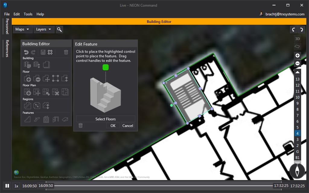
U-shaped stairs are stairwells that extend through the entire building and connect on every floor. The floors that a stairwell connects to can be changed after placing the stairs. To place U-shaped stairs, press the “Stair” button and select U-shaped, then place the pin in the visualizer to mark the center of the stairwell. The stairs can then be scaled and rotated with the control handles. Click inside the feature and drag to move it to a new location. The U-shaped stair feature should cover the entire stairwell, including landings. To change the floors which have the stairwell, click “Select Floor” in the feature toolbox and deselect floors as needed. If there is another building above or below the one currently being edited, the stairwell can be made to extend into it with this tool.
Escalators
Much like the straight staircases, escalators can connect two floors or regions. The controls for editing an escalator are exactly the same as for straight stairs and ramps.
Elevators
Similar to U-shaped stairs, to place an elevator, click the “Feature” button and then place the yellow pin inside the building. This will bring up a small box with control handles. Use these control handles to stretch, scale, and rotate the elevator. Click and drag inside the elevator to move it. By default, elevators will extend through the entire building and appear on every floor. To change this, click “Select Floors”, then deselect floors from the list. If there is a building above or below the one currently being edited, the elevator can be extended into this building.
Entrances
When placing an entrance, there will be two main control points. One of these control points will be placed outside on the terrain and the other will be placed inside. Entrances connect terrain to a single floor that the user chooses, although multiple entrances can be placed on multiple floors.
Ramps
Similar staircases and escalators, ramps connect two floors or regions. After clicking the “Feature” button, place the top of the ramp on the appropriate floor, then choose the lower floor and place the bottom of the ramp. Further editing of the ramp can be done with the same method as for straight stairs.
Miscellaneous
This section will cover some overall components of the building editor as well as some of the tools that are a bit less obvious.
Save / Discard / Delete
After any change has been made to a building, the “Save” button will be enabled. A prompt will confirm continuation.
The “Discard” button will remove any edits made to the building in the current editing session. If the building is currently being created, “Discard” will remove the new building.
The “Delete” button will completely remove the currently selected building. This action cannot be undone. In order to confirm deleting a building, users must type in the command after pressing the “Delete” button. Deleting a building will also delete data associated with it such as features, floor heights, and map status. Any maps or tracks that were taken inside the building will no longer display properly in 3D.
Add Marker
The “Add Marker” tool will place a pin to a set location. The pin will persist until the editing session is complete and will be visible on top of all other layers. To do this, right-click where the pin should go, then select “Add Marker”. This tool is useful as a known location for building outlines or lining up floor plans. Right-click on the marker for the option to remove it.