Complex Buildings
The NEON 11 update made large improvements to the control users have when creating their buildings. Buildings can be designed in NEON Command to resemble real life more accurately, which means tracking with NEON can be more accurate than ever. Not only can tracking be more accurate, but complex buildings such as convention centers and transit hubs are now much easier to model and track in.
This article will walk through the creation of a complex building. It will show you the various tools needed for most accurate building creation as well as going through the best practices for creating your buildings. The Stamp Student Union at the University of Maryland in College Park will be used for this tutorial.
Create Building Outline
To begin, start the Building Editor by clicking on “Tools > Create Building” or right click on the map and select “Create Building”. In the Building Editor, you will see an orange banner at the top as well as the Building Editor Toolbox.
The first step of creating a building is to draw the outline. Click the corner points along the outline of the building to create it. Many buildings have roofs of different heights, and it can be confusing as to which to follow. The easiest method is the use whichever roofline is furthest from the center of the building. Later in the tutorial, you will clean up this outline for each floor.
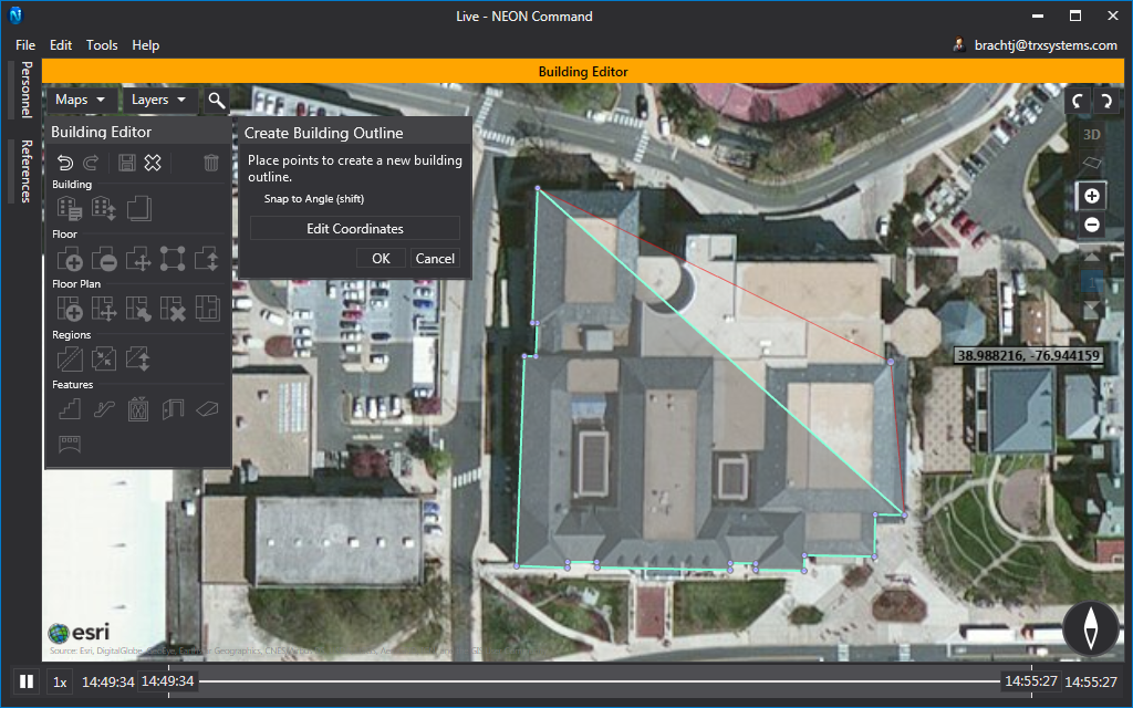
Press “Shift” to have your current outline point snap to angles at 15-degree increments. This will help your building look much cleaner in the end. If a mistake is made, Undo and Redo functionality is available on the Toolbox, or via the CTRL-Z and CTRL-Y hotkeys.
Finish outline creation by clicking the “OK” button on the Toolbox, or by pressing the “Enter” key. Upon creation of the initial building outline, a dialog will pop up for entering building information.
Building Details
The building details dialog allows you to enter building information such as the name, number of floors, number of basements, and the labels for floors. All buildings are required to have a name and at least 1 floor above. The primary floor is included in the above floors, it is the floor that intersects the terrain by default, and it is colored orange in the Labels.
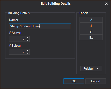
For the Stamp Student Union, set 2 floors above and 2 floors below. Then, in the Labels box, relabel the floors to be “2”, “1”, “G”, “B1”, in descending order. Click “OK” to finish.
Edit Layout
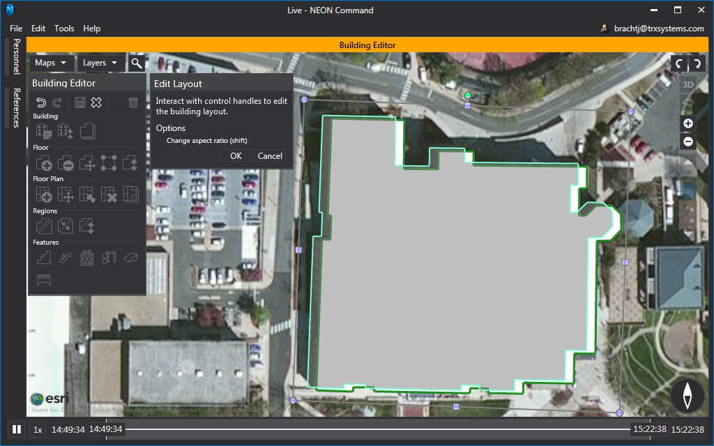
Almost all satellite images are taken from at least a slight angle instead of directly above. This causes the roof to be offset from the base of the building, and in tall buildings, this offset can be drastic. If a building in NEON is offset from its proper location, it can cause a mismatch between GPS information and your indoor location. This is why it is important to align your outline with the base of the building.
To realign your building, click the “Edit Layout” button in the “Floor” section. Drag your outline so that it lines up with the base of your building. Typically, a corner of the building is the easiest to align. Click “OK” to confirm your placement, then click “Yes” on the confirmation dialog to apply this change to the other floors.
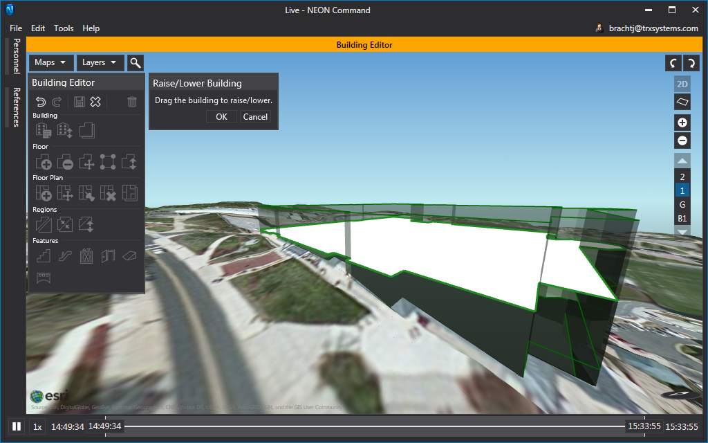
Raise/Lower Building
By default, NEON sets the elevation of your building equal to the highest terrain point on your outline. While this will not affect the accuracy of your tracking, it may look odd if this is not the actual elevation of the building. To fix this, you can raise or lower the building to better align it with the terrain.
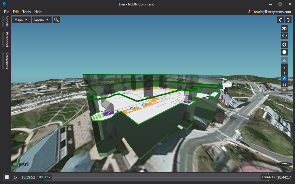
Click the “Raise/Lower Building” button in the toolbox to begin. This will change the visualizer to a 3D view. Now that it is in 3D, make sure terrain is enabled to properly adjust the height. The terrain button is shown in the image below. Click on your building and drag it up and down to adjust the height. Reference things like Google Street View or other pictures to determine the elevation of your building. The elevation of the Stamp Student Union is shown in the image below. Press “OK” to confirm your changes.
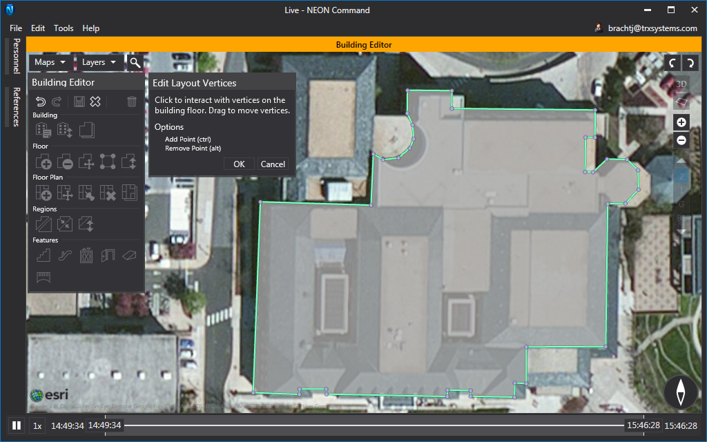
Edit Layout Vertices
Often times, like with the Stamp Student Union, different floors may have different outlines. It is important each floor is as accurate as possible. You can do this by editing your original outline by adding and deleting vertices or moving existing ones. Reference pictures or Google Street View to help determine different roof heights. If you are unable to determine outlines of individual floors, you can first add floor plans and then edit vertices to match the floor plan. It is only recommended you do this if you are sure your floor plans are accurate and to scale.
To start, select Floor 2 on the right side of the screen, and then click the “Edit Layout Vertices” button. Edit vertices to remove the sections in the North-West and South-East corners as shown in the picture below. Click and drag vertices to move them. You can also press “Ctrl” and click to add a vertex, and press “Alt” and click to remove one. Press “OK” to confirm the edits. The other 3 floors of the Stamp Student Union do not need to be modified. When prompted if you would like to apply your changes to the other floors, click “No”.
NOTE: If you are unable to remove a vertex, it is mostly like because removing that vertex will result in invalid geometry. Try moving the vertex to a new location before removing it, or remove other vertices first.
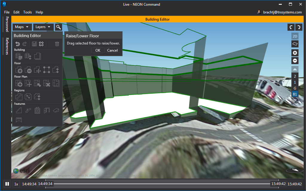
Raise/Lower Floor
Many buildings, such as convention centers, have floors that are much taller than average floors, or just taller than other floors in the building. To reflect this in NEON, you can raise or lower individual floors. This also helps if a building has entrances on multiple floors, but those entrances don’t align with the terrain in NEON.
The lower floor of the Stamp Student Union has an exit on the bottom floor, however, the building model does not currently extend down that far. To fix this, select floor “B1” and click the “Raise/Lower Floor” button. Click on the floor and then drag the floor down to meet the terrain where the entrance is.
Add Floor Plan
Now that the building is set, it is time to add floor plans which will allow you to accurately map and track. Many public buildings have floor plans available online. The floor plans to the Stamp Student Union can be found here. Be careful with public floor plans because they may not be properly to scale and may drastically affect your tracking experience.
Once you have your floor plans gathered, select a floor, and then click “Add Floor Plan”. In the file browser that pops up, select the floor plan for the floor you have selected and then click “Open”. The floor plan will be placed on the floor with the top facing North. Do not worry about the alignment yet, as you will edit it in just a moment. Repeat this for every floor.
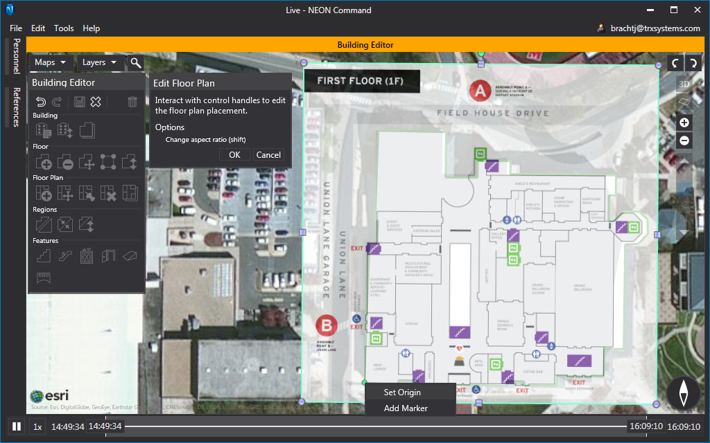
Edit Floor Plan
NEON Command offers 2 methods of editing the placement of your floor plan. The first is the standard image scale and translate operation. To do this, select the floor you would like to edit first, then click the “Edit Floor Plan” button.
The best way to start is to align a building corner in the floor plan with the appropriate corner of your outline. Try to choose a corner that you know is accurate in your outline. The walls likely won’t line up exactly, but that is fine right now. With your corner in place, right-click and select “Set Origin”. With the origin set, all scaling and rotation will happen about that point. Translating your floor plan will move your origin.
With your origin set, stretch and rotate your floor plan into place. Click and drag the control handles to scale your floor plan. If your floor plans are not already to scale, press and hold “Shift” to change the aspect ratio. Click and drag green circle control handle to rotate the image. Use these handles to align another point of your floor plan with the outline. Once you have 2 points aligned correctly, the rest of the floor plan will be in place.
Getting the floor plans and building to match perfectly the first time can be very difficult. This can be because the floor plan is not to scale or the outline is not correct. In the second case, you can now return to “Edit Layout Vertices” and edit your layout to match the floor plan better. If you choose to do this, make sure your floor plan is placed as accurately as possible before doing so.
Edit Floor Plan with Control Points
The second method of placing your floor plans is Control Points. Control Points allow you to see your building and floor plan side by side and then match known points of both to align them. Using control points will not preserve the aspect ratio. It will stretch the floor plan in order to align it with its points in the building. If you know your floor plan is scaled properly, avoid using this feature. The floor plans for the Stamp Student Union are not to scale.
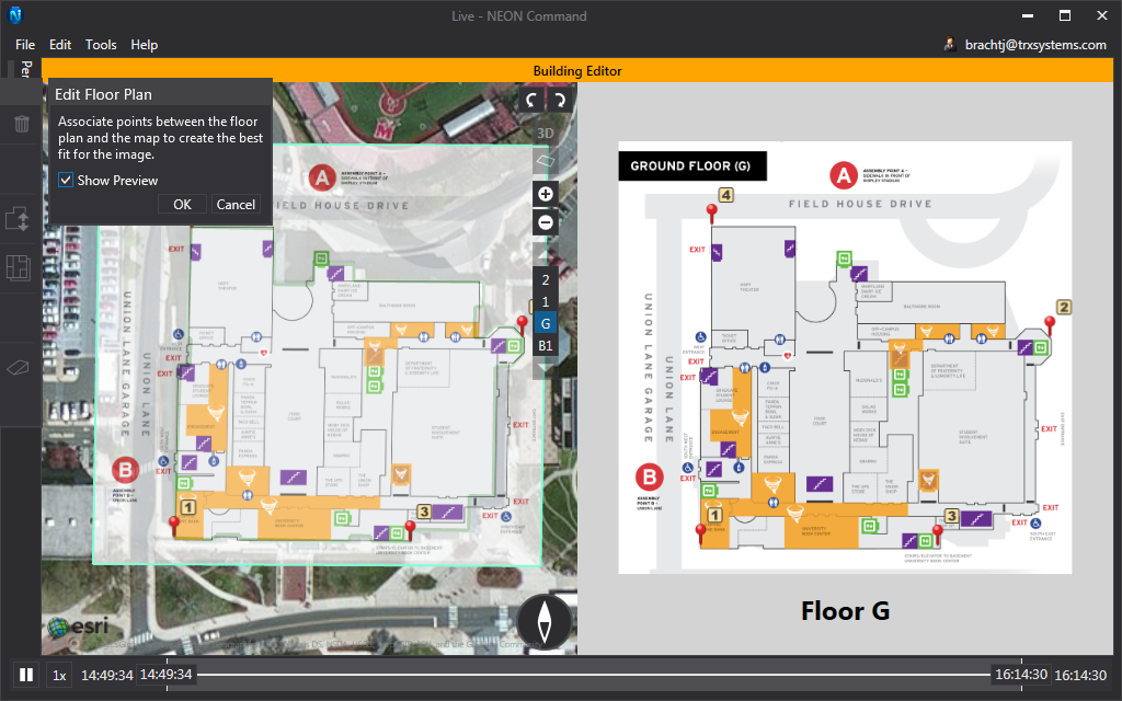
Begin by clicking the “Edit Floor Plan with Control Points” button. This changes your view to show the floor plan on the right, and the building on the left. First, click on a known location in the building. Corners are usually the best choice. Then click on the corresponding location on the floor plan. If you enable the Show Preview checkbox in the toolbox, a transparent floor plan will appear on the left to show how the floor plan now aligns. Continue placing control point pairs three or four more times or until the floor plan is properly aligned. Click “OK” to confirm your edits.
Using Control Points or the standard editor, continue to edit your floor plans on each floor until they are all aligned as accurately as possible.
Once all of your floor plans are in place, you can go back and use the Edit Layout Vertices tool to adjust your outline to better fit your floor plan.
Split Region
Many larger buildings have split level floors with stairs or ramps between them. Creating these regions in NEON will allow you to create the features between them and then use them as constraints while tracking. The floor plans of the Stamp Student Union do not show any of the split levels, but one can be used to represent a temporary stage.
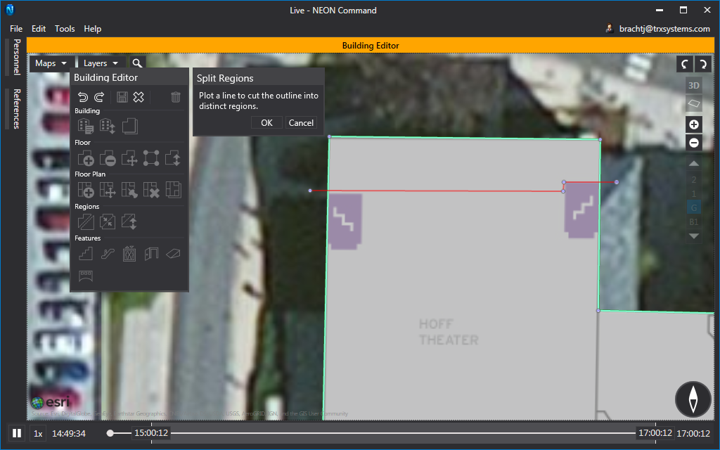
Select the ground floor of Stamp and click the Split Regions button to begin. The floor plan shows 2 small staircases in the Hoff Theater which we will assume lead up to a stage. We will create a region for this stage as shown in the image below. To do this with the Split Regions tool, click either on your outline or outside of it, and then click to place the other of the line. Continue to draw connected lines until you have traced out the stage as shown below. Any intersections will count as a region vertex, which means you can place 2 points outside on opposite sides of a building to make a region that spans across the whole building. Press “OK” to confirm your region. Any lines that are not a part of a polygon will be discarded when you press “OK”.
Raise/Lower Regions
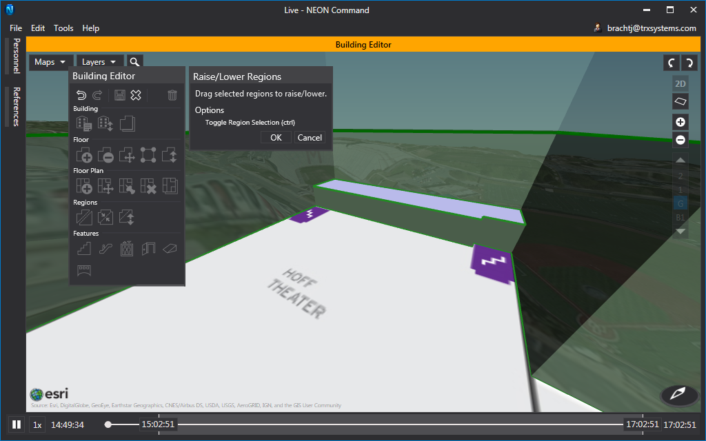
Now that you have a region, it is important to change its height for visual purposes. Click the “Raise/Lower Regions” button to begin, then click on the region that you just created to select it. If you are raising multiple regions at the same time, you can hold Ctrl to allow you to select multiple regions at once. With your region click and drag up a little bit to represent a height of 2 or 3 feet. Press “OK” to confirm the height of your region.
Add Features
NEON 11 added the ability for you to add structural features to your building such as stairs, escalators, elevators, ramps, building entrances, and skybridges. Once these features are added to your building they can improve your tracking accuracy by constraining your position as you walk through or on them.
Stairs
NEON allows you to create three different types of stairs: straight, U-shaped, and L-shaped. Straight stairs and L-shaped stairs can span between two floors or two regions. U-shape stairs are considered well features and span the entire height of the building by default.
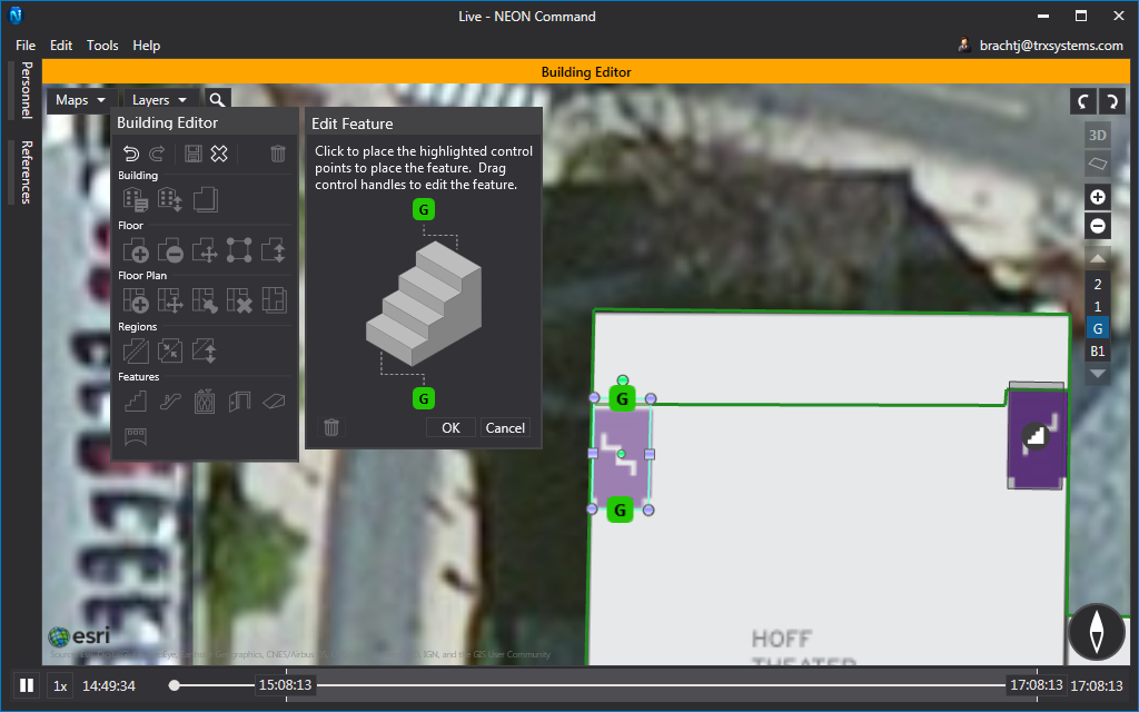
Add two straight stairs to each side of the region you just created to begin. Click the Stair icon and then select “Straight”. This will allow you to place the top, then the bottom of the staircase. After selecting “Straight,” first click into the region, just a bit from the side. Then click on the floor outside of the region, just a bit away. See the picture below for placement. Once both points have been placed, use the control handles to move, stretch, and scale the staircase. Click “OK” to confirm. Repeat this process for the other side of our region.
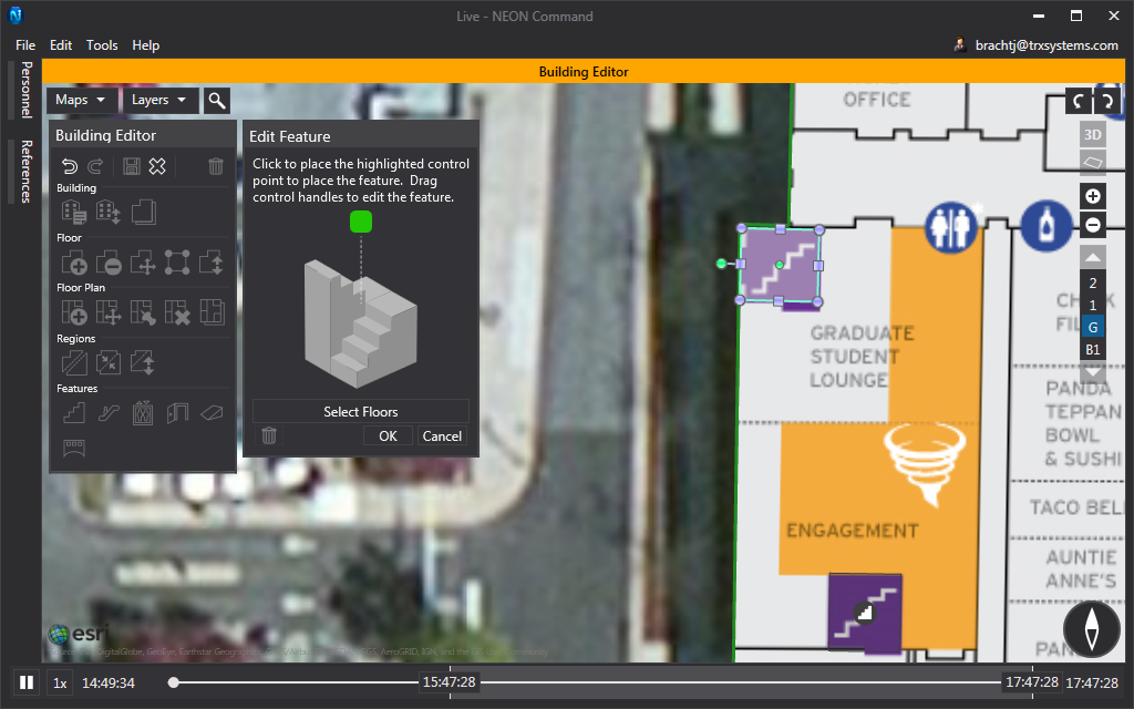
After adding your straight stairs, add the U-shaped stairwells where they are indicated on your floor plan. It is suggested that you use your most accurately placed floor plan for reference because these stairwells can be used later to clean up your building. Click the Stair icon and then select “U-Shaped”. Place the control point in the center of one of the stairwells indicated on the map. Use the control handles to move, stretch, and scale the stairwell to match your floor plan. Click “OK” to confirm. Repeat this process for all indicated stairwells.
Ramps
Ramps in NEON Command function very much the same way as straight stairs. Ramps are able to connect 2 regions or 2 floors. Placing ramps is also done the same way as straight stairs. There are no ramps in Stamp Student Union that need to be placed.
Elevators
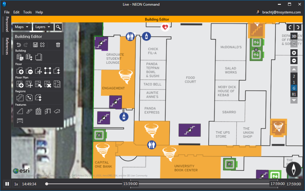
Elevators are considered to be well-features, which means that they will extend through every floor by default. To change this, you can click the “Select Floors” button in the elevator toolbox. If a building has an elevator bank it is OK to group 2 or 3 elevators into a single elevator feature as long as they are on the same side of the hallway. Do no group elevators that are not directly next to each other. Click the “Place Elevator” and then click on the floor plan to place it. Stretch and rotate the elevator and then click “OK” to confirm it. Repeat this to place all of the elevators on the floor plans.
Entrances
Entrances are used to connect your building to the terrain. As you enter or exit a building, the entrance will help to constrain your location. As a note, your avatar is still able to enter or exit a building even if there is no entrance placed in your building model.
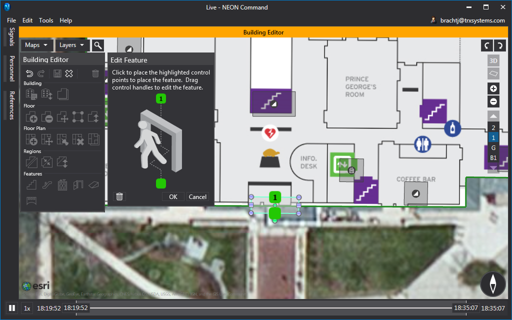
The floor plans used in this tutorial do not show the location of entrances, but a quick look at Google Street View can confirm them. To place an entrance, first select the correct floor and then click the “Entrance” feature button. First click inside the building to place one side of the entrance, and then click outside the building. Move and stretch the feature to match the building entrance. Don’t worry about creating a feature for each door. One feature is enough to cover a few doors in a row.
Skybridges
Skybridges can be used to connect 2 buildings between any floors. Stamp Student Union does not have any skybridge that need to be placed. In case you are working on a building that does have a skybridge, you can begin by selecting the correct floor of your building and then click the skybridge feature. Then click to place one end of the skybridge on your floor and then click again to place the other end of the skybridge somewhere out of the building. Once the skybridge is on the map, select your 2nd building and the floor the skybridge connects to. Drag and drop the outside end of the skybridge into a location on your second building and then click “OK” to confirm.
Complete
Now that you have added all of your floor plans, regions, and features, your building model is complete. Click “Save” in the building editor toolbox. Once you click save, you will need to confirm that you want to save all pending changes. After that, your building will automatically be uploaded to the cloud and will be available to view on all of your devices after a few seconds. If you want to later make changes to your building, right-click on it, and select the “Edit Building” option.